Sunday, April 11, 2010

Getting started with Arduino review


Author: Massimo Banzi
Publish date: Oct. 2008
First edition

This book gives you information about the way of Arduino or Arduino philosophy, this way starts when Mr. Benzie was teaching students and designers the basics of electronics, in other words he wanted to taught electronics to non-professionals. Mr. Benzie goes back to his earlier times when he learned electronics by work by practice not by theory; he realized that classes these days focus on theory more than practice. So in this book he clarifies the principles that should be followed in Arduino way and in tinkering for example, the author stated that "we love junk" (old electronic devices) we should play with those old devices and hack them to get new ideas such as keyboards we can disassemble them to get the small chip inside and try to hack it and make our input device to computer, after we make our device we can link it to any sensor and to computer.

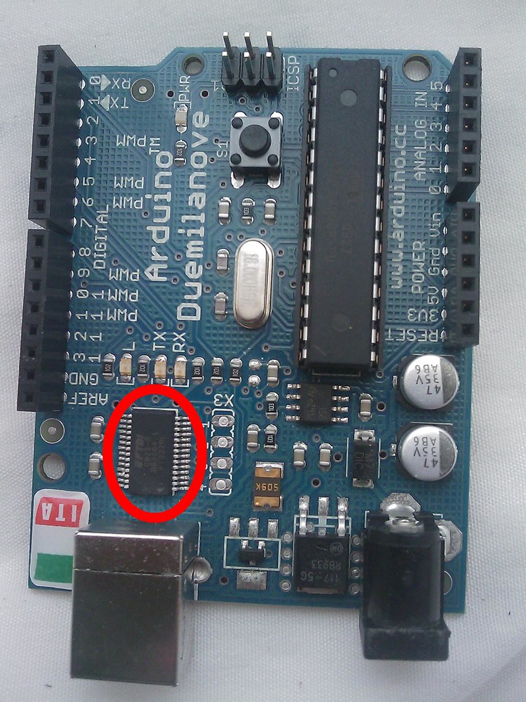
After clarifying Arduino way, there is a very good description about Arduino platform (the hardware and the software), the Arduino board (hardware) is a microcontroller (small computer), that receives instructions from Arduino IDE (software) and save inside it to apply the instructions always. These instructions will be converts to acts by Arduino I/O (In & Out) pins; the book has many examples about the inputs and outputs such as digital inputs & outputs, analog inputs & outputs. Finally there are examples about Arduino-Computer communications (serial communications).

In addition, there are many books mentioned in the book, Mr. Benzie recommend Tom Igoe’s “Making Things Talk” for learning about complex sensors also recommend “Low-tech Sensors and Actuators” by Adan Somali-Fischer & Usman Haque for learning about hacking low price toys.

In conclusion, we can say that the book focus on Arduino knowledge and the tinkering, hacking philosophy, on the information (how to use and get befits of Arduino) and the inspiration (how to understand and apply your ideas on technology).

Tuesday, April 6, 2010

Drawing Arduino in Google SketchUp 7

I tried to find Arduino Duemilanove in  3D Warehouse but did not find it, I found a model for Diecimila, I tried to make it by my self this is the result, it is not very good but maybe I will update it later.


I tried to upload it to 3D Warehouse but they only accept kmz files for Google Earth, 


Update: I knew now that I should upload it from inside SketchUp. Here is the download URL:
http://sketchup.google.com/3dwarehouse/details?mid=65ebac1e83702f15bf5a7d4d00dbf624

This is a picture of it:


Best Regards

Sunday, April 4, 2010

Say welcome to books

Today I received three electronic books I had bought earlier from Amazon, the books are:
Getting Started with Arduino.
MAKE: Electronics: Learning by Discovery.
Teach Yourself Electricity and Electronics, Fourth Edition.

This is my first impression of the books:

I had read a digital version of the first one (Getting Started with Arduino) but I like to read the paper book, it is very good for any one who wants to learn about Arduino and has many good and resourceful information in a friendly manner.


The second book (MAKE: Electronics: Learning by Discovery), is published by O'Reilly media and it is very good for electronics newbie, because it taught you by discovering not as the academic way, for example in many places in the book the author will ask you to do something in a wrong way to taught you how electricity works or to till you why we do this not that. I got this book because it is highly recommended by Make community and many DIY people, it is ranking No. #1  in Amazon Electrical & Electronics, in Robotics and in Robotics & Automation books.


The third one (Teach Yourself Electricity and Electronics, Fourth Edition), this one second bestseller in Electrical & Electronics books in Amazon, I like this book because it Combines electricity and electronics.

I will study these books and post my notes here. Thanks you everyone.

Wednesday, March 31, 2010

Arduino Components: Operational amplifier LM358

Op amp (Operational amplifier), can amplify the input voltage many times it might be millions of times. When I found the number LM358 in Arduino schematic twice I checked up the eagle board and found only one, physically I found one where is the other:
This photo from the schematic:

This photo for the LM358 in Arduino:


I realized that the LM358 is drawn that way in schematics, because it contain two pieces of Op amps, as in LM358 datasheet.

I might write a new post about LM358 in Arduino, I believe this book is very good to learn about Op amps "Op Amps for Everyone"

Conclusion, LM358 IC in Arduino contain two Op amps, this IC can be operated from one + input (no need for + and -).

Tuesday, March 30, 2010

Arduino components: the voltage regulator MC33269D-5.0

Arduino components: the voltage regulator MC33269D-5.0
Voltage regulating is very important in any electronic circuit, Arduino have a regulator to regulate the external power source, MC33269D-5.0 here is a photo (circled in red):


Written on the part: (has no relation with the part real number that I got from schematic)
117-5G
RB933

MC33269D family has many other regulators the number after the dash specify the model type of the regulator, in our case it is 5, in this model the output voltage is 5 Volts.  Other befits of the MC33269D-5.0 is that it can protect the circuit from thermal and short problems.
In other Arduino clone (Minimalist Arduino, ArduinoBreadboard and others) LM7805 is used instead of MC33269D-5.0, they are almost the same.
Vin voltage regulator MC33269D-5.0 in Arduino receive a 7V of power and convert it to stable 5V.

Monday, March 29, 2010

Arduino Components: The Mosfet (field-effect transistor) NDT2955

Mosfets used to switch electronic signals; it has three pins A, B and C, A can be connected to B by applying small current to pin C, but C is isolated from
A and B (this is the true magic).
This is a photo of the Mosfet NDT2955 in Arduino (circled in red)

There is no clear part number on the part, but I get the part number from Arduino EAGLE files and schematic, they are open source and free you can get your copy.
What is the rule of NDT2955 in Arduino, its datasheet clarifies the applications that NDT2955 fits in:
  • DC/DC converter
  • Power management

But in Arduino Duemilanove it works like a power source selector. In previous versions of Arduino (such as Diecimila or NG) there was a power selector jumper which the user will select which is the power source (external power or USB power). The old jumper location in Diecimila and NG was the same location of the Mosfet NDT2955 in Duemilanove.

In Arduino Duemilanove we do not need to switch the power between USB and external power, the Mosfet NDT2955 will select for us. If there is an external power supply and the Arduino Duemilanove is connected to the computer the NDT2955 will select the external power supply, if we turn off the external power supply the NDT2955 will chose the USB power.

Sunday, March 28, 2010

Arduino Components: FTDI FT232RL (USB/Serial Converter)


Arduino is not a USB 100% device, if we examine it we will find this information, Arduino is a Serial device but has the ability to be connected to the USB port. The FTDI FT232RL plays the rule of converting between Serial and USB protocols.
This is a photo of the FT232RL (Circled in red):


The data written on the chip are:
FTDI
0922-B
B63264.1
FT232RL

The idea of Arduino communication is: PC sends serial data via the USB port, FT232RL receive that data and convert them to their original state (Serial Data) and transfer them to the Arduino mind (AtMega328P), AtMega328P sends data to PC through FT232RL, so the FT232RL helps Arduino send & receive serial data through a USB port.

Nowadays serial ports are hiding from new PCs. FT232RL make it more convenient to plug your Arduino to almost all computers all over the world. Speed of data transfer for FT232RL is from 300 baud (300 bits per second) to 3 Mbaud, Arduino does not need more than 115200 baud, so when we write sketches in Arduino IDE we specify the baud speed for example:
 
void setup() {
Serial.begin(9600);         // opens serial port, sets data rate to 9600 bps
}
 
void loop() {}
We mention the speed as 9600 baud.
 
FT232RL can (as it stated in datasheet) be found in many devices 
such as bar code readers, cameras, mp3 players, smart card readers and many other electronic devices.

Serial communication is very good for Arduino family, its simplicity enable us to implement Arduino in many applications the serial communication through a USB interface is an excellent feature of Arduino.

Saturday, March 27, 2010

Arduino Components: The ICSP 6-pin header

The ICSP pin header is the six pins that are showed in this photo;


It is even clarified by written those pins are for ICSP, but what does ICSP mean and what are its benefits. First ICSP (In-Circuit Serial Programming) is a way that allows us to program the chips when they are in circuits, in Arduino it helps in programming Arduino chip (AtMega328P) directly with AVR instructions without the need to Arduino IDE, in this case we can program AtMega328P as the factory programmed Arduino with bootloader. The bootloader helps Arduino device to understand sketches (Arduino applications), and to run them once they are installed in Arduino.

ICSP will help us upgrade our Arduinos in case there are any updates from Arduino team. Arduino team make ICSP like that to allow them make any update in the last minute before sending the device to the customer, in other words they manufacture Arduino without programming it with bootloader, they continue updating the bootloader from time to time, and before sending Arduino to a customer they install the last version of the bootloader.

Other good thing about Arduino ICSP is that it can turn an Arduino to an IPS programmer to program, a general ISP (In-System Programming) programmer if we see this project by Massimo Banzi (co founder of Arduino) http://tinker.it/now/2006/12/04/turn-arduino-into-an-avr-isp-programmer/, he just changed the Arduino crystal and some modifications in Arduino program and turn it to programmer.

Conclusion, ICSP is a way to program Arduino, or an advantage to use Arduino as an ISP programmer.

Wednesday, March 24, 2010

Arduino Components: The Crystal oscillator


Learning in general starts with two questions; How? and Why?, how makes the learner as an imitator or one of a million, why enable your creativity, improve your experiences and make you unique. As a newbie in electronics Arduino is very good in terms of prototyping and making projects in an easy manner. Actually all websites that I read to learn Arduino and electronics focus on how to make this project and HOW to solve that problem. I was looking for more details about the physical components on Arduino, not finding much information about them encourage me write this series: we will start with
Arduino Crystal oscillator:


(The crystal inside the red square)
Arduino crystal helps Arduino dealing with time issues, for example if we build a project that turns a switch A off after 15 minutes on and turn on switch B, C & D one after another with a 20 minutes step. We can use Arduino software to program Arduino to do that, but how Arduino calculate the time? The answer is by using crystal, the number on the top of Arduino crystal is 16.000H9H this gives us information about the frequency which is 16,000,000 Hertz or 16 Mhz, this small component can make 16 millions cycles per second so using this concept Arduino can calculate time.

Furthermore, using this crystal is important in other applications such as microprocessors, webcams, computers, inside my computer motherboard there are two crystals; here is a photo:


Before knowing how crystals works, I thought that computer calculate time using algorithms (Now I understand that computer uses algorithms with crystals to detect time).

Still two questions, why Arduino team select a 16 Mhz crystal and do not use a 32Mhz or more? We have to look in the datasheet of (Arduino brain), ATmega328P: http://www.atmel.com/dyn/resources/prod_documents/8271S.pdf in the first page under "Speed Grade" it has been Clearfield that the maximum frequency should not exceed 20 Mhz, so the 16 Mhz is suitable.

The second question is; What about the crystal accuracy? This depends on the crystal specifications'. Arduino crystal have a 100ppm accuracy, in other words these crystals have an error margin 100 cycles – or + in each one million cycles, this means that the maximum – or + error in time calculated by Arduino is 30 seconds per a year.

Tuesday, March 23, 2010

More About Load Cells' indicators

Indicator is very important in scale applications. Beside its role in amplifying the values that it get from load cell and counting the deal load, it can be programmed to deal with more than one source of raw materials.
At the indicator that I have, there is an ability to control 4 sources of raw materials (some indicators can control 8 sources or more), it can send data to computer through RS232 or RS485 ports.
Because it can send data to RS485 port, there is a good chance to use load cells at a 1200 meters distance
To control the outer sources we should use a buffering Relay and a Diode between the Indicator and the power supply.
This photo for the back of the indicator that we can connect four wires for the material sources:

We can connect wires to the M1, M, M3, M4. Then program the indicator with the weight of each material, when the material reach that point the indicator will send a signal to turn off the relay and turn on another relay so the second material will be loaded to the storage hopper.
This is the wiring schematic recommended by the manufacturer:

I think this will help automate many batching tasks.

Monday, March 22, 2010

More about Load Cells

I will write today and tomorrow about the Load Cells and indicators, and will switch to something else.

All load cell manufacturers and sellers give the buyer a copy of the load cell data sheet, It might be attached inside the package of the load cell. In brief, Load Cells do not have many data that should be written in the data sheet, so my load cell data sheet is only two pages, in the first page information about the applications that the load cell used in. The second page are the technical information, dimensions and wiring.
Have a look to the technical information:

Inside the red line is "Output Sensitivity" which means the highest output (in Volts or mV) of the load cell when it carries the maximum load. Actually this depends on the input value in the photo above the output is 2 mV/V, my input volts are 10 V, so the highest output will be 20 mV when there is a 5 tons under the load cell (because my load cell maximum capacity is  tons), can I increase the input voltage? Yes until 15 V as stated in the technical above in "Excitation Voltage", what will happen if we increase the input more than the 15 V, nothing will happen under 20 V as in the data sheet "Maximum Excitation" except that the indicator will show an error message, if we increase the input voltage more than 20 V, it is not stated what will happen but maybe there will be some problems, small components inside the load cell will be damaged maybe.
I tried to increase input to 16 V and got an error message, of course I did not tried to increase more than the 20 V.

Arduino can not communicate directly with load cells, because Arduino have an analog input that read values between 0 and 5V, between 0 and 5V Arduino can read 1023 values, so can read each 0.0049 V and convert it to 1, for example 2.5V will be read as 512 in Arduino analog input and 5V will be 1023. So the small output numbers of the Load Cell (0 to 20m/V) will not be easy for Arduino to read, so we should use amplifier between the load cell and Arduino.